VNH3SP30 Motor Driver Carrier MD01B
Pololu item #: 705
This carrier board for ST’s VNH3SP30 motor driver IC operates from 5.5 to 16 V and can deliver a continuous 9 A (30 A peak). It offers built-in protection against reverse-voltage, over-voltage, under-voltage, over-temperature, and over-current and makes a great general-purpose motor driver.
Overview
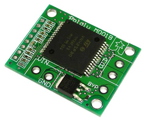
This module is a compact breakout board for ST’s high-power VNH2SP30 or VNH3SP30 motor driver IC, each of which is a fully integrated H-bridge that can be used for bidirectional speed control of a single brushed DC motor. The basic operation of the driver is summarized below, but we also recommend careful reading of the VNH2SP30 datasheet (283k pdf) or VNH3SP30 datasheet (228k pdf) before using this product. The board incorporates most of the components of the typical application diagram on page 8 of the VNH2SP30 datasheet, including pull-up and current-limiting resistors and a FET for reverse battery protection. It ships fully populated with its SMD components, including the VNH2SP30 or VNHSP30 motor driver IC, as shown in the product picture.
General specifications
- Motor driver: VNH3SP30
- Motor channels: 1
- Minimum operating voltage: 5.5 V
- Maximum operating voltage: 16 V1
- Continuous output current per channel: 9 A
- Peak output current per channel: 30 A
- Maximum PWM frequency: 10 kHz
- Reverse voltage protection?: Y

Real-world power dissipation considerations
The motor drivers have maximum current ratings of 30 A continuous. However, the chips by themselves will overheat at lower currents (see table above for typical values). The actual current you can deliver will depend on how well you can keep the motor driver cool. The carrier printed circuit board is designed to draw heat out of the motor driver chips, but performance can be improved by adding a heat sink. In our tests, we were able to deliver short durations (on the order of milliseconds) of 30 A and several seconds of 20 A without overheating. At 6 A, the chip gets just barely noticeably warm to the touch. For high-current installations, the motor and power supply wires should also be soldered directly instead of going through the supplied terminal blocks, which are rated for up to 15 A.
Many motor controllers or speed controllers can have peak current ratings that are substantially higher than the continuous current rating; this is not the case with these motor drivers, which have a 30 A continuous rating and a over-current protection that can kick in as low as 30 A (45 A typical). Therefore, the stall current of your motor should not be more than 30 A. (Even if you expect to run at a much lower average current, the motor can still draw high currents when it is starting or if you use low duty cycle PWM to keep the average current down.)
Reverse-battery protection
The motor driver boards include an N-channel MOSFET for reverse-battery protection. This component keeps the motor driver from destroying itself if the input power is accidentally connected backwards. However, this component does slightly increase the total resistance between your battery and your motor. For slightly improved performance, the MOSFET can be bypassed by connecting the negative battery terminal to the bypass pin. (This terminal will also need to be connected to your logic supply ground.)
Documents