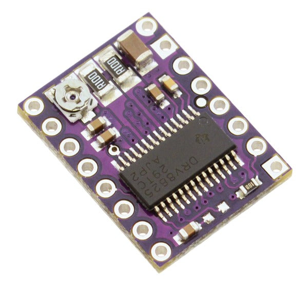
DRV8825 Stepper Motor Driver Carrier, High Current
£14.39
inc VAT
Original price
£11.99
-
Original price
£11.99
Original price
£11.99
£11.99
-
£11.99
Current price
£11.99
ex VAT
SKU DRV8825-BRK
Pololu item #: 2132

Control inputs
Each pulse to the STEP input corresponds to one microstep of the stepper motor in the direction selected by the DIR pin. These inputs are both pulled low by default through internal 100kΩ pull-down resistors. If you just want rotation in a single direction, you can leave DIR disconnected.
The chip has three different inputs for controlling its power states: RESET, SLEEP, and ENBL. For details about these power states, see the datasheet. Please note that the SLEEP pin is pulled low by default through a 1MΩ pull-down resistor, and the RESET and ENBL pins are both pulled low by default through internal 100kΩ pull-down resistors. This means that RESET and SLEEP will be preventing the driver from operating if left disconnected. Both of these pins must be pulled high to enable the driver (they can be connected directly to a logic “high” voltage between 2.2 and 5.25 V, or they can be dynamically controlled via connections to digital outputs of an MCU). The default state of the ENBL pin is to enable the driver, so this pin can be left disconnected.
The DRV8825 also features a FAULT output that drives low whenever the H-bridge FETs are disabled as the result of over-current protection or thermal shutdown. Otherwise, the pin is floating, so you will need to use a pull-up resistor to give it a default high state if you want to use this pin. Note that there is a 1.5k protection resistor in series with the pin that you should take into account when selecting your pull-up resistor (i.e. it should probably be at least 10k). This 1.5k series resistor means it is safe to connect this pin to a logic high voltage, as might happen if you use this board in a system designed for the pin-compatible A4988 carrier.
Current limiting
To achieve high step rates, the motor supply is typically much higher than would be permissible without active current limiting. For instance, a typical stepper motor might have a maximum current rating of 1 A with a 5Ω coil resistance, which would indicate a maximum motor supply of 5 V. Using such a motor with 12 V would allow higher step rates, but the current must actively be limited to under 1 A to prevent damage to the motor.
The DRV8825 supports such active current limiting, and the trimmer potentiometer on the board can be used to set the current limit. One way to set the current limit is to put the driver into full-step mode and to measure the current running through a single motor coil without clocking the STEP input. The measured current will be 0.7 times the current limit (since both coils are always on and limited to approximately 70% of the current limit setting in full-step mode).
Another way to set the current limit is to measure the voltage on the “ref” pin and to calculate the resulting current limit (the current sense resistors are 0.100Ω). The ref pin voltage is accessible on a via that is circled on the bottom silkscreen of the circuit board. The current limit relates to the reference voltage as follows:
Current Limit = VREF * 2
So, for example, if the reference voltage is 0.5 V, the current limit is 1 A. As mentioned above, in full step mode, the current through the coils is limited to 70% of the current limit, so to get a full-step coil current of 1.5 A, the current limit should be 1.5 A/0.7=2.1 A, which corresponds to a VREF of 2.1 A/2=1.05 V. See the DRV8825 datasheet for more information.
Note: The coil current can be very different from the power supply current, so you should not use the current measured at the power supply to set the current limit. The appropriate place to put your current meter is in series with one of your stepper motor coils.
Power dissipation considerations
The DRV8825 driver IC has a maximum current rating of 2.5 A per coil, but the current sense resistors further limit the maximum current to 2.2 A, and the actual current you can deliver depends on how well you can keep the IC cool. The carrier’s printed circuit board is designed to draw heat out of the IC, but to supply more than approximately 1.5 A per coil, a heat sink or other cooling method is required.
This product can get hot enough to burn you long before the chip overheats. Take care when handling this product and other components connected to it.
Please note that measuring the current draw at the power supply will generally not provide an accurate measure of the coil current. Since the input voltage to the driver can be significantly higher than the coil voltage, the measured current on the power supply can be quite a bit lower than the coil current (the driver and coil basically act like a switching step-down power supply). Also, if the supply voltage is very high compared to what the motor needs to achieve the set current, the duty cycle will be very low, which also leads to significant differences between average and RMS currents. Additionally, please note that the coil current is a function of the set current limit, but it does not necessarily equal the current limit setting. For example, in full-step mode, the coil current is internally limited to 70% of the set maximum, so you would set the current limit to around 2.1 A to get a coil current of 1.5 A.
Documents