QTR-1RC Reflectance Sensor
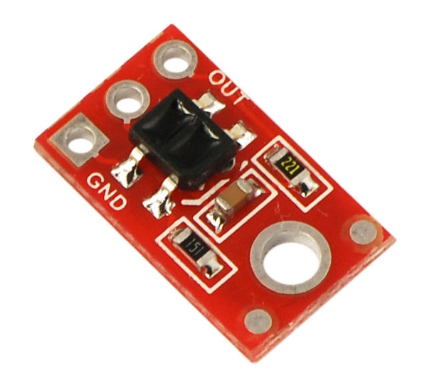
The QTR-1RC reflectance sensor carries a single infrared LED and phototransistor pair in an inexpensive, tiny 0.5" x 0.3" module that can be mounted almost anywhere and is great for edge detection and line following applications. The output is designed to be measured by a digital I/O line.
Functional Description
The Pololu QTR-1RC reflectance sensor carries a single infrared LED and phototransistor pair. The phototransistor uses a capacitor discharge circuit that allows a digital I/O line on a microcontroller to take an analog reading of reflected IR by measuring the discharge time of the capacitor. Shorter capacitor discharge time is an indication of greater reflection.

The LED current-limiting resistor is set to deliver approximately 20-25 mA to the LED when VIN is 5 V. The current requirement can be met by some microcontroller I/O lines, allowing the sensor to be powered up and down through an I/O line to conserve power.
Because of its small size, multiple units can easily be arranged to fit various applications such as line sensing and proximity/edge detection. For a line sensor with eight of these units arranged in a row, please see the QTR-8RC reflectance sensor array.
Specifications
- Dimensions: 0.3" x 0.5" x 0.1" (without header pins installed)
- Operating voltage: 5.0 V
- Supply current: 25 mA
- Output format: digital I/O compatible
- Optimal sensing distance: 0.125" (3 mm)
- Maximum recommended sensing distance: 0.375" (9.5 mm)
- Weight without header pins: 0.008 oz (0.23 g)
Interfacing the QTR-1RC Output to a Digital I/O Line
Like the Parallax QTI, the QTR-1RC module has sensor outputs that require a digital I/O line capable of first charging the output capacitor (by driving the line high) and then measuring the time for the capacitor to discharge through the phototransistor. This measurement approach has several advantages, especially when multiple units are used:
- No analog-to-digital converter (ADC) is required
- Improved sensitivity over voltage-divider analog output
- Parallel reading of multiple sensors is possible with most microcontrollers
The typical sequence for reading a sensor is:
- Set the I/O line to an output and drive it high
- Allow at least 10 us for the 10 nF capacitor to charge
- Make the I/O line an input (high impedance)
- Measure the time for the capacitor to discharge by waiting for the I/O line to go low
These steps can typically be executed in parallel on multiple I/O lines.
With a strong reflectance, the discharge time can be as low as several dozen microseconds; with no reflectance, the discharge time can be up to a few milliseconds. The exact time of the discharge depends on your microcontroller’s I/O line characteristics. Meaningful results can be available within 1 ms in typical cases (i.e. when not trying to measure subtle differences in low-reflectance scenarios), allowing up to 1 kHz sampling.