Pololu 5V, 6A Step-Down Voltage Regulator D24V60F5
Sold out
£17.40
inc VAT
Original price
£14.50
-
Original price
£14.50
Original price
£14.50
£14.50
-
£14.50
Current price
£14.50
ex VAT
SKU D24V60F5-PSU-BRK
This synchronous switching step-down (or buck) regulator takes an input voltage of up to 38 V and efficiently reduces it to 5 V while allowing a typical continuous output current of up to 6 A. Typical efficiencies of 80% to 95% make this regulator well suited for higher-power applications like powering motors or servos, while high efficiencies are maintained at light loads by dynamically changing the switching frequency, and an optional shutdown pin enables a low-power state with a current draw of a few hundred microamps.
Features
- Input voltage: 5 to 38 V (see below for more details on the regulator’s dropout voltage, which affects the low end of the operating range)
- Fixed 5 V output (with 4% accuracy); this can be lowered by adding an external resistor between FB and VOUT
- Typical maximum continuous output current: 6 A
- Integrated reverse-voltage protection, over-current protection, over-temperature shutoff, soft-start, and under-voltage lockout
- Typical efficiency of 80% to 95%, depending on input voltage and load; the switching frequency automatically changes at light loads to maintain high efficiencies
- 800 μA typical no-load quiescent current; can be reduced to 10 µA to 20 µA per volt on VIN by disabling the board
- “Power good” output indicates when the regulator cannot maintain its set output voltage
- Compact size: 1.6″ × 0.8″ × 0.3″ (40.6 × 20.3 × 7.6 mm)
- Four mounting holes for #2 or M2 screws
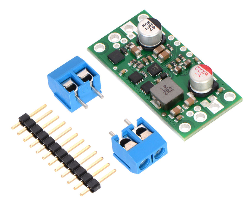
- Smaller holes for 0.1″ header pins and larger holes for terminal blocks offer several options for connecting to the board
Using the regulator
This boost regulator has six connections: input voltage (VIN), ground (GND), output voltage (VOUT), feedback (FB), ENABLE, and power good (PG).
The input voltage, VIN, powers the regulator and can be supplied with voltages up to 38V. The effective lower limit of VIN is VOUT plus the regulator’s dropout voltage, which varies approximately linearly with the load from around 500 mV to a little over a volt (see below for graphs of dropout voltages as a function of the load).
The output voltage, VOUT, is set to 5V by default. The output voltage can optionally be lowered by adding a resistor between the FB pin and VOUT as detailed in the Decreasing the output voltage section below.
The regulator is enabled by default: a 100 kΩ pull-up resistor on the board connects the ENABLE pin to reverse-protected VIN. The ENABLE pin can be driven low (under 0.6 V) to put the board into a low-power state. The quiescent current draw in this sleep mode is dominated by the current in the pull-up resistor from ENABLE to VIN and by the reverse-voltage protection circuit, which will draw between 10 µA and 20 µA per volt on VIN when ENABLE is held low. If you do not need this feature, you should leave the ENABLE pin disconnected.
The “power good” indicator, PG, is an open-drain output that goes low when the regulator’s output voltage falls below 90% of what it is set to (i.e. 4.5 V with the default 5 V output setting). An external pull-up resistor is required to use this pin.