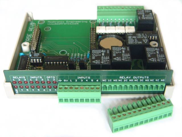
Input-Output-Relay board with enclosure and battery backed RTC
Description
The IOR5E is an Input-Output-Relay board with an enclosure and battery backed RTC. It has space for a Modtronix compact SBC board to be mounted as a daughter board. To control the outputs and relays, and read inputs, is has to be used together with a Modtronix compact SBC board. No SBC board is included with the IOR5E! Matching enclosure rear panels are available for the supported SBC board. The SBC board used depends on the type of PIC CPU and interface required. Currently the following Modtronix compact SBC boards can be used together with the IOR5E board and enclosure:
- SBC65EC: The SBC65EC can be used as the daughter board to enable the IOR5E to be accessed via Ethernet. The "Back view with SBC65PC Daughter board" picture below shows what the back of the enclosure looks like when this SBC board and it's matching enclosure rear panel are used. The "Front panel for SBC65EC Daughter board" picture below shows the enclosure rear panel that is used with the SBC65EC.
- SBC68EC: The SBC68EC can be used as the daughter board to enable the IOR5E to be accessed via Ethernet. The "Back view with SBC65PC Daughter board" picture below shows what the back of the enclosure looks like when this SBC board and it's matching enclosure rear panel are used. The "Front panel for SBC65EC Daughter board" picture below shows the enclosure rear panel that is used with the SBC65EC.
- SBC28PC-IR2: The SBC28PC-IR2 can be used as the daughter board to enable the IOR5E to be accessed via RS232 or CAN BUS. The "Back view with SBC28PC Daughter board" picture below shows what the back of the enclosure will look like when this SBC board and it's matching enclosure rear panel are used. Seeing that this SBC board can be configured for RS232 or CAN BUS, it can be used together with either the RS232 or CAN BUS enclosure rear panel.
- SBC28PC-IR4: The SBC28PC-IR4 can be used as the daughter board to enable the IOR5E to be accessed via RS485 or CAN BUS. The "Back view with SBC28PC Daughter board" picture below shows what the back of the enclosure will look like when this SBC board and it's matching enclosure rear panel are used. Seeing that this SBC board can be configured for RS485 or CAN BUS, it can be used together with either the RS485 or CAN BUS enclosure rear panel.
Any use of this module is at your own risk! Always take necessary safety precautions when working with high voltages to prevent electrical shock! SK Pang Electronics will take no responsibility for any damage or personal injury incurred due to using this unit with high voltages!
Features
- Fully assembled and delivered with enclosure and screws
- Compact size enclosure, 130mm long, 100mm wide, 30mm high
- 5 Relay outputs rated at 30V. Relays are rated at 7A at 250VAC. All relay outputs have 3 terminals, Normally closed, Common and Normally Open. Using the relay outputs for voltages higher than 30V is at your own risk! SK Pang Electronics will take no responsibility for any damage or personal injury incurred due to using this unit!
- 4 Opto isolated inputs rated at 30V. Opto coupler ICs are rated at 5300 VAC input isolation. The inputs are all diode protected. The opto couplers are all socketed, and can be replaced if damaged. They switch on at approximately 2V, and have been tested to voltages up to 50V. Using the opto coupler inputs for voltages higher than 30V, placing external resistor in series with the opto inputs to use higher voltages or making any other modifications to this unit is at your own risk! SK Pang Electronics will take no responsibility for any damage or personal injury incurred due to using this unit!
- 5 Analog or Digital inputs (5V or 26V). Inputs 1 to 5 are connected to port pins A0, A1, A2, A3 and A5 of the SBC board. These ports are analog inputs on most PIC processors, and can thus be used as Analog or Digital input.
- 1 Counter or Digital input (5V). Input 6 is connected to port pins A4 of the SBC board. A4 is connected to PIC Timer0's clock input on most PIC processors, and can thus be used as a Digital or Counter input.
- 6 Digital outputs (5V). Inputs 1 to 6 can alternatively be used as digital outputs! Each output has a 2k2 series resistor.
- Inputs 1 to 4 can be configured via straps to be 5V or 26V inputs
- Resistor dividers on inputs 1 to 4 uses high accuracy 0.25% resistors
- All connectors use 8A pluggable 3.81mm screw type terminal blocks, and can easily be plugged in to the module. The IOR5E is supplied with all terminal block plugs fitted!
- Software controlled LED for power indication
- 15 Software controlled LEDs for indicating the status of all Relays, Inputs and Outputs
- Assembled with high accuracy 20ppm RTC 32.432kHz crystal
Battery holder for RTC backup battery. Typical battery life will be about 10 years. - IC socket for assembling DS1307 real time clock
- 3 pin molex connector for accessing RS232 signal on SBC daughter board. A CAB3S6FT Serial Port Cable is required to connect to a DTE serial port (like the serial port on a PC).
Supplied with Rear Panel, select:
Ethernet board for use with SBC65EC or SBC68EC
CAN-BUS board for use with SBC28PC-IR4 or SBC28PC-IR2