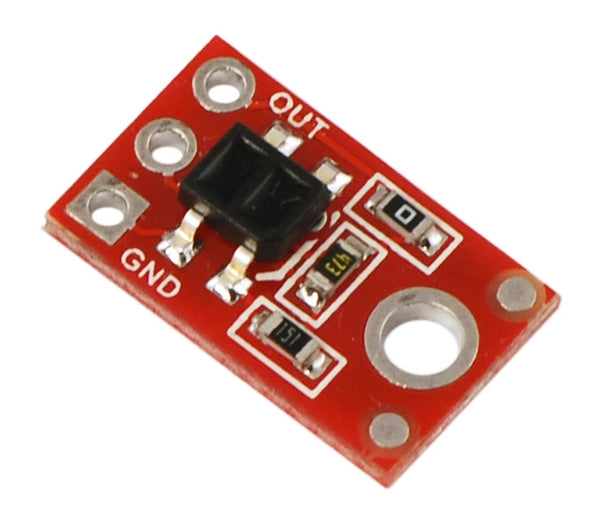
QTR-1A Reflectance Sensor
The QTR-1A reflectance sensor carries a single infrared LED and phototransistor pair in an inexpensive, tiny 0.5" x 0.3" module that can be mounted almost anywhere and is great for edge detection and line following applications. The reflectance measurement is output as an analog voltage.
Functional Description
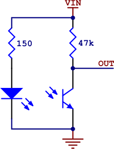
The Pololu QTR-1A reflectance sensor carries a single infrared LED and phototransistor pair. The phototransistor is connected to a pull-up resistor to form a voltage divider that produces an analog voltage output between 0 V and VIN (which is typically 5 V) as a function of the reflected IR. Lower output voltage is an indication of greater reflection.

The LED current-limiting resistor is set to deliver approximately 20-25 mA to the LED when VIN is 5 V. The current requirement can be met by some microcontroller I/O lines, allowing the sensor to be powered up and down through an I/O line to conserve power.
Because of its small size, multiple units can easily be arranged to fit various applications such as line sensing and proximity/edge detection. For a line sensor with eight of these units arranged in a row, please see the QTR-8A reflectance sensor array.
Specifications
- Dimensions: 0.3" x 0.5" x 0.1" (without header pins installed)
- Operating voltage: 5.0 V
- Supply current: 25 mA
- Output format: analog voltage
- Output voltage range: 0 to supplied voltage
- Optimal sensing distance: 0.125" (3 mm)
- Maximum recommended sensing distance: 0.25" (6 mm)
- Weight without header pins: 0.008 oz (0.23 g)
Interfacing with the QTR-1A Output
- There are several ways you can interface with the QTR-1A output:
- Use a microcontroller’s analog-to-digital converter (ADC) to measure the voltage.
- Use a comparator with an adjustable threshold to convert the analog voltage into a digital (i.e. black/white) signal that can be read by the digital I/O line of a microcontroller.
- Connect the output directly to the digital I/O line of a microcontroller and rely upon its internal comparator.
This last method will work if you are able to get high reflectance from your white surface as depicted in the left image, but will probably fail if you have a lower-reflectance signal profile like the one on the right.
